Understanding what are common defects in steel pipes is essential for safe design, reliable production, and informed purchasing decisions. Defects may appear during steelmaking, forming, welding, heat treatment, or transportation. Typical examples include cracks, laminations, lack of fusion, incomplete penetration, pits, corrosion, dents, ovality, and excessive wall-thickness variation.
The damage is not always visible. A pipe may look smooth while ultrasonic testing reveals a planar separation beneath the surface. A weld can appear acceptable yet contain incomplete penetration at its root. Paul E. Mix, a respected nondestructive testing author, states, “The purpose of nondestructive testing is to detect and evaluate discontinuities without harming the part.” This principle remains practical in modern pipe inspection.
Experienced inspectors combine visual checks with dimensional measurement, ultrasonic testing, radiography, magnetic particle testing, or hydrostatic testing. The correct method depends on pipe grade, manufacturing route, service pressure, and applicable standards such as API 5L or ASTM specifications. A small pit on an external surface may be harmless in one application but critical after repeated pressure cycles. Context matters.
This guide focuses on visible clues, hidden flaws, and the inspection methods used to confirm them. It also recognizes an uncomfortable truth: inspection is not perfect. Equipment settings, surface scale, operator judgment, and poor records can produce misleading results. That is why reliable evaluation requires trained personnel, calibrated instruments, traceable reports, and careful review rather than a single quick test.
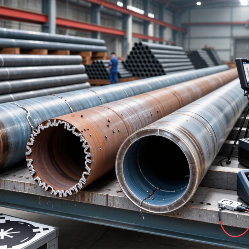
Steel pipe defects are easier to assess when classified by origin: surface, dimensional, or internal. Surface flaws include seams, laps, corrosion pits, and scratches. Look closely at weld zones and pipe ends, where handling damage can hide beneath scale. A pit may appear minor, yet reduce the wall locally. Visual inspection helps locate it, but cannot confirm its depth. ISO 10893-5 describes magnetic-particle testing for detecting surface imperfections in seamless and welded steel tubes. For nonmagnetic materials, other inspection methods may be needed. The method must fit the material.
Dimensional defects include excessive ovality, uneven wall thickness, and out-of-tolerance diameter or length. Measure at several points, not just one convenient spot. A caliper can reveal ovality; ultrasonic thickness measurement can map thin areas. Acceptance limits depend on product specification, grade, and dimensions. API Specification 5L sets requirements for line pipe, including dimensions and inspection; its limits should be checked against the order rather than assumed universal.
Internal defects, such as laminations, inclusions, and incomplete weld fusion, may be invisible from outside. ISO 10893-8 covers automated ultrasonic testing for laminar imperfections in seamless and welded tubes. Radiography or ultrasonic testing can examine welds, but each has limits. No single test catches everything. And records matter: note location, size, method, and uncertainty. I have seen a clean-looking pipe mislead an inspector; visual confidence is not evidence.
A useful visual inspection starts with a clean, dry pipe surface and steady lighting. Rotate the pipe where practical, and examine the body, weld seam, and ends. Look for cracks, laminations, gouges, dents, corrosion pits, and visible weld irregularities. A shallow mark may be harmless, but its depth and location matter. Small marks matter.
Use API 5L as the governing reference, not a substitute for careful observation. Check the applicable edition, pipe grade, and purchase requirements before judging an indication. Acceptance depends on the specified requirements and how a surface imperfection is evaluated; a visual check alone cannot confirm every condition. Do not guess. Record the pipe identification, defect location, approximate length and depth, and inspection conditions. Clear photographs with a scale can help reviewers compare findings.
When a mark appears questionable, keep it separate from accepted material until qualified personnel assess it against the applicable criteria. Avoid grinding or covering the area before documenting it, since that can remove useful evidence. In practice, lighting angles and surface residue can make a shallow scratch look severe—or hide a real indication. That uncertainty is easy to underestimate. Reinspect the area after cleaning, and escalate ambiguous findings rather than treating appearance as proof.
How to Identify Common Defects in Steel Pipes
Verify Wall Thickness Against the API 5L −12.5% Tolerance Limit
Wall thickness is a critical inspection point because a thin section can reduce a pipe’s pressure capacity. API Specification 5L sets a −12.5% tolerance from the specified nominal wall thickness for applicable pipe dimensions. For example, a pipe specified at 10.0 mm should not measure below 8.75 mm under that limit. Confirm the applicable edition, product grade, diameter, and measurement requirements before accepting or rejecting material; requirements can differ by product specification and order conditions.
Use a calibrated ultrasonic thickness gauge, following a recognized procedure such as ASTM E797/E797M. Clean the surface, apply couplant, and take readings at several positions around the circumference and along the pipe. A single reading can miss a shallow, localized thin spot. Record the lowest reliable value, its location, instrument calibration details, and the nominal thickness. Compare results with the project’s acceptance criteria, not just a convenient average.
Tips: Check near welds, pipe ends, and visibly corroded areas. Recheck suspicious readings after cleaning and repositioning the probe. Small differences matter. Surface roughness or poor probe contact can distort results, so judgment is still required. API 5L and ASTM E797/E797M provide the technical basis; the inspection record should make the measurement method and decision traceable.
The chart compares ultrasonic wall-thickness readings with the API 5L negative tolerance limit for a pipe with a 10.00 mm specified wall thickness. The minimum acceptable thickness is 87.5% of nominal, or 8.75 mm.
Readings below the red limit line indicate a potential wall-thickness nonconformance and should be verified according to the applicable inspection procedure. Localized low readings may indicate corrosion, pitting, laminations, or manufacturing variation.
Steel pipes can appear flawless on the outside while hiding laminations, inclusions, cracks, or incomplete bonding. These defects may reduce pressure resistance and grow during forming or service. Visual inspection alone cannot reveal them. ASTM E213 ultrasonic testing provides a practical method for examining metal pipe and tubing below the surface.
During testing, an ultrasonic probe sends high-frequency sound through a couplant and into the pipe wall. Reflections return when the sound meets a discontinuity. Technicians compare these signals with responses from a calibrated reference standard containing known reflectors. The pipe is scanned along its length, while coupling, surface condition, probe alignment, and scanning speed remain controlled. Small changes matter.
A strong signal does not automatically identify the defect type. It only indicates a change in sound transmission. Experienced inspectors review signal amplitude, position, shape, and repeatability. They also check suspicious areas from another direction when the procedure allows it. A clean trace is not proof of perfect steel. Poor coupling can hide a flaw, and excessive surface scale can create misleading noise. That limitation deserves attention. Test records should include equipment settings, calibration checks, scan coverage, and signal locations. Final acceptance must follow the applicable specification, purchase requirements, and qualified personnel’s evaluation.
| Defect Type | Typical UT Indication | Common Location | Likely Formation Cause | Potential Effect on Service | Risk Level | Recommended Follow-Up |
|---|---|---|---|---|---|---|
| Longitudinal Crack | Sharp, repeatable loss of the back-wall echo or a strong reflected signal aligned with the pipe axis. | Weld zone, heat-affected zone, or longitudinally stressed areas of the pipe body. | Welding stress, inadequate fusion, hydrogen-related cracking, or excessive forming strain. | May cause rapid leakage or rupture, especially under cyclic pressure or corrosive service. | High | Confirm with repeat scans from both directions; characterize length and depth; isolate the pipe pending engineering disposition. |
| Lamination | Broad, planar internal indication with reduced or interrupted back-wall response; signal may remain stable during circumferential scanning. | Mid-wall region of the pipe body, often parallel to the rolling plane. | Nonmetallic inclusions, shrinkage cavities, or incomplete consolidation during steel production. | Reduces effective wall continuity and may affect welding, forming, or pressure containment. | High | Map the indication in two dimensions and measure its extent; compare results with the applicable product specification and acceptance criteria. |
| Lack of Fusion | Distinct reflector near the weld fusion boundary, frequently accompanied by a localized back-wall echo reduction. | Longitudinal or circumferential weld fusion line. | Insufficient heat input, incorrect welding parameters, surface contamination, or poor edge preparation. | Creates a planar weakness that can grow under pressure, vibration, or repeated loading. | High | Scan from multiple angles and use weld-specific evaluation procedures; repair or reject when the indication exceeds the governing criteria. |
| Incomplete Penetration | Linear indication centered at the weld root with a characteristic loss of transmission through the root area. | Root of a welded joint. | Insufficient root gap, low heat input, incorrect electrode or wire positioning, or unsuitable welding technique. | Acts as a stress concentrator and may initiate fatigue cracking or localized leakage. | High | Verify with focused weld scanning and, when required, complementary surface or radiographic examination before acceptance. |
| Slag Inclusion | Irregular or elongated internal reflector with variable amplitude and inconsistent shape along the weld. | Weld metal or the interface between successive weld passes. | Trapped welding slag caused by inadequate cleaning, low interpass control, or unsuitable welding parameters. | Decreases weld strength and can become a starting point for crack growth. | Medium | Determine the indication length, height, and position; compare with the applicable weld acceptance standard. |
| Porosity | Multiple small, rounded echoes or scattered indications with limited continuity during probe movement. | Weld metal, sometimes distributed in clusters. | Gas entrapment from moisture, contamination, inadequate shielding, or unstable arc conditions. | Usually reduces local strength; clustered or interconnected porosity can significantly affect pressure integrity. | Medium | Assess the number, size, spacing, and clustering pattern; use the relevant acceptance limits for the pipe application. |
| Inclusion in Pipe Body | Localized internal reflector that may produce a weak, irregular echo and a partial reduction in back-wall amplitude. | Pipe body, commonly parallel to the material working direction. | Nonmetallic particles retained in the steel during melting, casting, or rolling. | Can initiate cracking during forming or service, particularly under cyclic or corrosive loads. | Medium | Rescan at different angles and record the indication coordinates, amplitude, and estimated dimensions for disposition. |
| Undercut-Related Crack | Near-surface linear indication at the weld toe, often stronger when scanned from the affected side. | External or internal weld toe. | Excessive welding current, incorrect travel speed, poor electrode angle, or inadequate weld profile. | May develop into a fatigue crack under vibration, pressure cycling, or bending stress. | High | Evaluate surface condition and crack depth; remove surface contamination before confirming the indication with a suitable complementary method. |
| Internal Pitting or Corrosion Loss | Reduced back-wall echo, multiple reflections, or unstable signals caused by an irregular internal surface. | Internal pipe surface, especially in areas exposed to water, chlorides, acids, or stagnant fluids. | Electrochemical corrosion, erosion-corrosion, deposits, or inadequate internal protection. | Decreases remaining wall thickness and may lead to leakage or burst when the minimum wall is exceeded. | High | Measure the remaining wall thickness on a grid, identify the minimum value, and compare it with the required design or inspection thickness. |
| Wall Thickness Variation | Gradual or localized change in time-of-flight or back-wall position during circumferential scanning. | Pipe body, weld transition, ends, or areas affected by forming and machining. | Uneven rolling, eccentricity, forming misalignment, localized wear, or excessive material removal. | Creates nonuniform stress distribution and may reduce the pressure margin at the thinnest location. | Medium | Perform calibrated thickness mapping and document minimum, maximum, and average wall values. |
| End Cracking | Strong linear or branching indication near the pipe end, sometimes with edge-related signal interference. | Cut ends, beveled ends, threaded areas, or heat-affected end regions. | Thermal cutting, end forming, machining stress, hydrogen effects, or handling damage. | May propagate from the end during welding, pressure testing, or service loading. | High | Inspect the end region from multiple directions and supplement with a surface examination after cleaning or re-machining. |
| Geometric Echo or False Indication | Repeatable signal caused by a weld profile, bevel, pipe end, curvature, or surface condition rather than a material flaw. | Weld cap, weld root, pipe ends, diameter transitions, or areas with rough coupling conditions. | Component geometry, probe alignment, surface roughness, poor coupling, or incorrect gain settings. | Generally no direct service effect, but misinterpretation can lead to unnecessary repair or rejection. | Low | Recheck with adjusted probe position, scanning direction, calibration, and coupling; verify whether the signal follows the component geometry. |
How to Identify Common Defects in Steel Pipes
Under ISO 3183, defect severity should be ranked against defined acceptance requirements, not visual appearance alone. A shallow scratch may be acceptable, while a smaller crack can threaten pipe integrity. Inspectors should examine dents, laminations, undercuts, arc burns, corrosion pits, and incomplete weld fusion. Every indication needs location, length, depth, and orientation records. Not every indication is a defect.
A practical screening method uses three levels. Level one covers minor imperfections within specified limits, verified by measurement. Level two includes uncertain or borderline indications that require calibrated ultrasonic, magnetic, or radiographic testing. Level three covers cracks, unacceptable weld discontinuities, severe wall loss, or dimensions outside the permitted range. These levels are an internal risk tool, not an official ISO ranking. The applicable edition, product specification, pipe grade, and purchaser requirements must control the final decision. I have found that rushed visual acceptance creates more disputes later. That weakness deserves attention.
Tips: Clean the surface before inspection. Measure pit depth with a verified gauge. Mark each indication on a traceable inspection record. Compare results with the exact acceptance table, not memory. If readings conflict, repeat the test and involve a qualified inspector. Calibration drift is easy to overlook.
Clean and dry the surface first. Use steady lighting. Rotate the pipe when practical. A clean surface helps.
Check for cracks, laminations, gouges, dents, corrosion pits, and uneven weld areas. Small marks matter. Their depth and location can change the decision.
Not always. Measure or estimate its depth and record its exact location. Lighting and residue can mislead. Reinspect after cleaning.
Record the pipe identification, defect location, approximate size, inspection conditions, and photographs. Use a scale in photographs. This helps reviewers compare findings.
Keep it separate from accepted material until qualified personnel complete the evaluation. Do not grind or cover the mark first. That may remove useful evidence.
Use a calibrated ultrasonic thickness gauge and a recognized measurement procedure. Apply couplant properly. Take readings around the circumference and along the pipe length.
A single reading may miss a small, localized thin area. Check near welds, pipe ends, and corrosion. Record the lowest reliable measurement. Compare it with the specified tolerance and project requirements.
No. Internal laminations, inclusions, cracks, and bonding problems may remain invisible. Outside appearance is not proof.
A probe sends high-frequency sound through couplant and the pipe wall. Reflections may indicate a discontinuity. Inspectors compare signals with a calibrated reference standard.
No. It shows a change in sound transmission, not a confirmed defect type. Review signal position, shape, amplitude, and repeatability. Poor coupling can hide flaws, so judgment remains necessary.
Common steel pipe defects can be grouped by where they originate: surface imperfections, dimensional deviations, and flaws hidden within the pipe wall. Understanding what are common defects in steel pipes helps inspectors choose the right checks and judge whether a pipe is suitable for its intended use. Visual inspection can reveal issues such as cracks, laps, seams, corrosion, and other visible irregularities; findings should be assessed against the applicable API 5L criteria.
Dimensional checks should compare measured wall thickness with specified requirements, including the stated −12.5% tolerance limit where applicable. Because internal flaws may not be visible from the outside, ultrasonic testing performed in accordance with ASTM E213 can help identify discontinuities within the material. Finally, defects should be ranked by their location, size, and potential effect on pipe performance, then evaluated against the relevant ISO 3183 acceptance requirements. Combining these methods provides a structured approach to identifying and assessing common pipe defects.

Dactron Pipe