Top Methods to Test Steel Pipe Strength?

Time:2026-09-19 Author:Henry
0%

Steel pipe strength cannot be judged by appearance alone. A pipe may look flawless while containing weak welds, wall-thickness variation, or hidden inclusions. This is why engineers ask how to test steel pipe strength before approving material for service. The answer depends on the pipe grade, manufacturing process, dimensions, and intended pressure.

Metallurgist George F. Vander Voort has stated, “Testing is only as good as the specimen, method, and measurement.” That principle fits steel pipe evaluation closely. A reliable program often combines tensile testing, hydrostatic pressure testing, hardness checks, bend testing, and ultrasonic inspection. Tensile testing reveals yield strength and ultimate tensile strength. Hydrostatic testing exposes leakage or pressure-related defects. Ultrasonic testing can identify internal discontinuities without cutting the pipe. Visual inspection still matters. Small surface cracks can become serious under repeated loading.

Details matter.

Technicians should verify calibration records, specimen orientation, test temperature, and wall-thickness measurements. Relevant standards may include ASTM A370, API 5L, or project-specific specifications. However, no single test proves complete performance. I have seen inspection plans become too focused on one impressive number, especially tensile strength. That approach can miss corrosion, poor weld fusion, or inconsistent dimensions. Results should be reviewed against acceptance criteria by qualified personnel, with traceable equipment and documented procedures. Even then, testing has limits. Sound engineering requires cautious interpretation, repeat checks when results appear unusual, and a clear connection between laboratory evidence and real operating conditions.
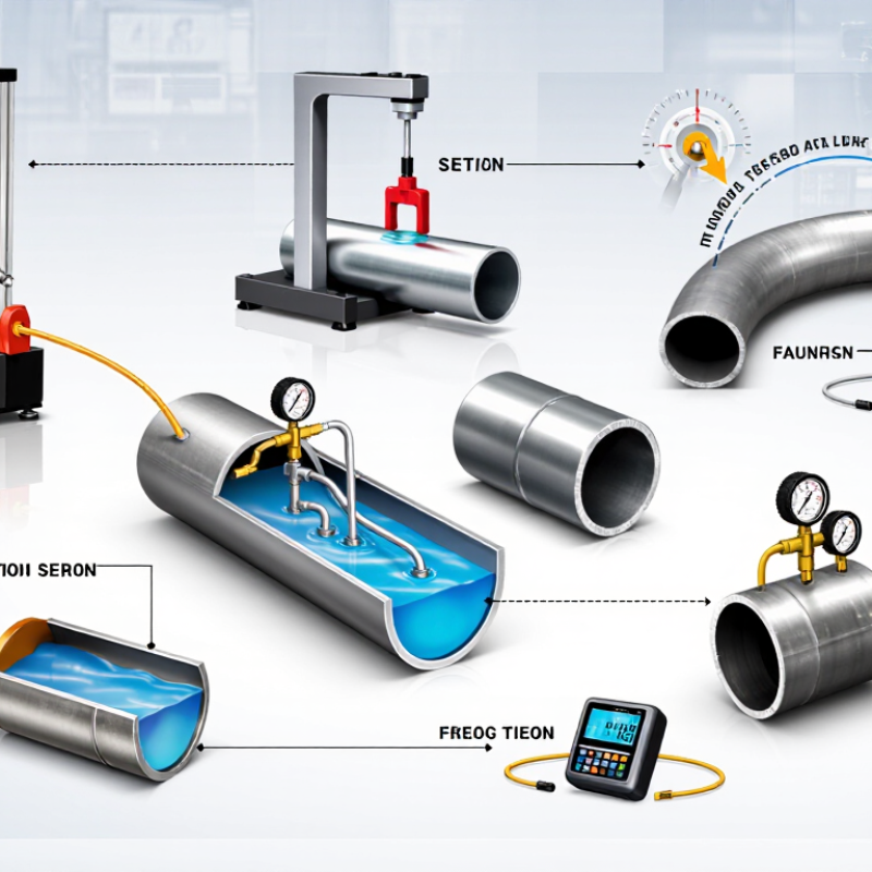
Top Methods to Test Steel Pipe Strength?

Steel Pipe Strength Testing: Purpose, Standards, and Preparation

Steel Pipe Strength Testing: Purpose, Standards, and Preparation

Steel pipe strength testing verifies whether a pipe can withstand pressure, bending, tension, and service loads. The correct method depends on its grade, diameter, wall thickness, and intended application. Tensile testing measures yield strength and ultimate strength. Hydrostatic testing checks pressure resistance and leakage. Flattening and bend tests reveal weaknesses near the weld or pipe surface. No test is perfect.

Testing should follow the specification selected for the pipe. Common references include ASTM A370 for mechanical testing, ISO 6892-1 for tensile testing, and ISO 8492 for flattening tests. Impact testing may follow ISO 148 when low-temperature toughness matters. Always confirm the latest edition and acceptance limits. A familiar standard can still be applied incorrectly.

Preparation often decides the quality of the result. Inspect the pipe surface and record heat number, dimensions, grade, and manufacturing condition. Calibrate testing machines before use. Cut specimens carefully, avoiding excessive heat that may change the steel structure. Keep samples clearly identified. Clean water is important for hydrostatic tests, especially when corrosion could distort observations. Test operators should document temperature, loading speed, pressure duration, and visible defects. Small details matter. I would also review unusual results instead of rejecting them immediately; sampling errors and preparation flaws sometimes explain a surprising failure.

Inspecting Steel Pipe Material, Dimensions, and Surface Condition

Steel pipe strength testing begins before loading the pipe. Inspect the material certificate, heat number, chemical analysis, and mechanical results. Confirm the grade matches the purchase specification. Tensile strength and yield strength reveal load-bearing behavior. Hardness testing provides a useful cross-check. It is not a substitute for tensile testing. Small sampling errors matter. A mislabeled section can invalidate otherwise careful results.

Measure outside diameter at several positions with calibrated calipers or diameter tape. Check wall thickness around the circumference using ultrasonic equipment or a micrometer. Record ovality, taper, straightness, and local dents. Thin areas often control pressure performance. Do not rely on one reading. Temperature, surface scale, and operator pressure can affect measurements. Compare results with the specified tolerance and service design. A pipe may look robust while losing strength through uneven wall reduction.

Inspect the surface under strong, angled light. Look for cracks, seams, laminations, corrosion pits, gouges, and arc marks. Clean loose scale before judging defects. Magnetic particle or liquid penetrant testing can locate surface-breaking flaws. Ultrasonic inspection can reveal internal discontinuities. However, every method has limits. Rough corrosion can create confusing indications. Repeat questionable readings and document photographs, locations, instruments, and calibration status. Good inspection is traceable, but field judgment still needs review.

Conducting Tensile, Yield Strength, and Elongation Tests

Top Methods to Test Steel Pipe Strength

Conducting Tensile, Yield Strength, and Elongation Tests

Steel pipe strength testing begins with a carefully prepared tensile specimen. Technicians cut samples longitudinally or transversely, depending on the pipe specification. They remove burrs and measure width, thickness, and gauge length with calibrated tools. Small dimensional errors can affect the final calculation.

The specimen is placed in a universal testing machine and pulled at a controlled rate. Tensile strength records the highest stress before fracture. Yield strength shows when permanent deformation begins. Some steels display a clear yield point, while others require a defined offset method. The testing standard must be selected before loading begins.

Elongation is measured after fracture by matching the broken sections. The technician compares the final gauge length with the original length. A longer extension usually indicates better ductility, but the fracture location matters. A break near the grip can make the result unreliable. Repeat tests improve confidence, although they cannot repair poor sampling.

Look closely at the fracture surface. A fine, fibrous appearance may suggest ductile failure, while a flatter surface deserves further examination. In practice, even experienced teams can overlook ovality or uneven wall thickness. Recording temperature, machine calibration, specimen orientation, and failure location makes the report more trustworthy. Results should be compared with the applicable technical specification, not judged from one number alone.

Top Methods to Test Steel Pipe Strength: Tensile, Yield Strength, and Elongation Tests
Test Method Primary Property Applicable Standard Typical Specimen and Dimensions Main Test Conditions Reported Data Illustrative Steel Pipe Result
Uniaxial Tensile Test Tensile strength, yield strength, and elongation ASTM E8/E8M or ISO 6892-1 Longitudinal strip, round bar, or full-section specimen cut from the pipe. A common proportional gauge length is L0 = 5.65√S0 under ISO practice. Axial loading at controlled strain or stress rate until fracture. The specimen is aligned carefully to reduce bending. Yield strength or 0.2% proof strength in MPa;
tensile strength in MPa;
percentage elongation after fracture.
Yield strength: 355 MPa
Tensile strength: 510 MPa
Elongation: 27%
Yield Strength Test Yield point or proof strength ASTM E8/E8M, ISO 6892-1, or ASTM A370 Machined or flattened longitudinal specimen taken from the pipe wall. The reduced section must be free from visible cracks, excessive machining marks, and distortion. Load is increased gradually while force and extension are recorded. For steels without a clear yield point, the 0.2% offset method is normally used. Upper yield strength, lower yield strength, or 0.2% proof strength; stress–strain curve and permanent strain reference. 0.2% proof strength: 355 MPa
Elastic modulus from curve: approximately 200 GPa
Tensile Strength Test Maximum stress before fracture ASTM E8/E8M or ISO 6892-1 Standard tensile specimen removed parallel or transverse to the pipe axis. A representative strip may be approximately 25 mm wide, subject to the applicable product standard and pipe wall thickness. Continue tensile loading beyond yield until the specimen reaches its maximum load and then fractures. Tensile strength, maximum force, fracture location, and stress–strain response. Maximum force: 127.5 kN
Tensile strength: 510 MPa
Fracture: outside the grip area
Elongation After Fracture Test Ductility and plastic deformation capacity ISO 6892-1, ASTM E8/E8M, or ASTM A370 Gauge marks are applied over the specified gauge length before testing. A common gauge length is 50 mm for many flat specimens, or a proportional gauge length based on the original cross-sectional area. The separated specimen halves are carefully fitted together after fracture. The final gauge length is measured without forcing the fractured surfaces together. A = [(Lu − L0) / L0] × 100, where L0 is the original gauge length and Lu is the final gauge length. Original gauge length: 50.0 mm
Final gauge length: 63.5 mm
Elongation: 27%
Transverse Ring or Full-Section Tensile Test Strength of the pipe in the circumferential direction ASTM A370 or the applicable pipe product standard A ring section or transverse strip is cut around the pipe circumference. The specimen dimensions depend on outside diameter, wall thickness, and the governing product standard. The specimen is loaded so that the principal tensile stress acts across the pipe circumference. Flattening, heating, or excessive straightening should be avoided unless specified. Transverse yield strength, tensile strength, elongation, and fracture behavior. Transverse yield strength: 360 MPa
Transverse tensile strength: 515 MPa
Elongation: 25%
Verification and Data-Quality Check Test validity and repeatability ASTM E8/E8M, ISO 6892-1, ASTM A370 Verify specimen identification, orientation, dimensions, gauge length, cross-sectional area, surface condition, and measurement equipment calibration. Confirm valid fracture location, stable machine alignment, correct test rate, complete force–extension data, and traceable calibration records. Dimensional tolerance, repeat-test variation, fracture position, extensometer data, and compliance status. Three specimens tested; tensile-strength spread: 8 MPa
Coefficient of variation: approximately 0.8%
Note: The illustrative results are technically plausible example values for a carbon-steel pipe and are not universal acceptance limits. Actual minimum strength and elongation requirements must be taken from the applicable pipe product specification, steel grade, pipe dimensions, specimen orientation, and purchase requirements.

Performing Hydrostatic, Burst, and Pressure Resistance Tests

Top Methods to Test Steel Pipe Strength

Hydrostatic testing is the practical starting point for steel pipe verification. Technicians fill the pipe with clean water, remove trapped air, and raise pressure gradually. The pressure and holding time should follow the purchase specification, API 5L, or ISO 3183. Inspectors watch for leaks, sweating, permanent deformation, and pressure loss. Water is preferred because it stores less energy than compressed gas. That difference matters when a test fails.

Burst testing pushes a prepared pipe section beyond its intended operating pressure. It reveals the actual failure mode, such as seam rupture, crack growth, or ductile tearing. Engineers record burst pressure, fracture location, wall thickness, and material properties. Pressure-resistance testing often combines repeated pressure cycles with dimensional checks. These cycles can expose weaknesses that a single hydrostatic test misses. The test plan should reflect service temperature, corrosion allowance, and loading conditions.

Tips: Calibrate gauges before testing. Use two independent pressure readings. Keep air out. Record water temperature and pipe dimensions. The 2016 NACE IMPACT study estimated corrosion costs at 2.5 trillion dollars annually, or 3.4% of global GDP. That figure supports serious inspection planning, but it does not predict one pipe’s life. My practical concern is simple: a passing pressure test can still hide poor weld quality or future corrosion. Pair pressure results with ultrasonic thickness measurements, weld inspection, and traceable records.

Analyzing Test Results and Verifying Structural Safety

Steel pipe strength testing is useful only when results are interpreted against the pipe’s actual service conditions. Tensile tests reveal yield strength, ultimate strength, and elongation. Hydrostatic tests expose leaks and weak weld areas under controlled pressure. Bend tests show whether the pipe can tolerate forming without cracking. Ultrasonic inspection can locate internal flaws that surface checks miss. No single test tells the whole story.

Tips: Record temperature, wall thickness, test pressure, loading speed, and specimen location. Compare each result with the project specification and applicable engineering standard. A high tensile value does not guarantee structural safety if corrosion has reduced the wall. Check ovality, dents, weld geometry, and support conditions. Small details matter.

Engineers should review the complete evidence, not only the highest passing number. For example, a pipe may survive pressure testing but fail after repeated vibration or external bending. Field measurements should be checked against laboratory results, with questionable readings retested when practical. Experienced inspectors also examine test equipment calibration and sampling methods. I have found that inconsistent records often reveal more than a single low result. Safety margins should reflect uncertainty, loading changes, and possible deterioration. Analysis is never perfectly clean; that limitation deserves honest attention before approval.

Top Methods to Test Steel Pipe Strength

Tensile testing identifies yield and ultimate tensile strength, while hydrostatic testing, flattening or bending tests, and buckling analysis verify pressure and structural resistance. The curve below uses representative nominal properties for S355-class structural steel: an elastic modulus of approximately 200 GPa, a minimum yield strength of 355 MPa, and a typical ultimate strength within the 470–630 MPa range.

The plotted tensile response reaches the nominal yield level near 355 MPa and peaks at approximately 510 MPa before necking. Structural safety should be verified by comparing calculated stresses from hydrostatic pressure, bending, and buckling loads with the applicable design resistance and safety factors.

FAQS

Why is steel pipe strength testing necessary?

It checks resistance to pressure, bending, tension, and service loads. No single test reveals every weakness.

Which tests are commonly used for steel pipes?

Tensile tests measure yield strength, ultimate strength, and elongation. Hydrostatic tests check leakage and pressure resistance. Bend and flattening tests expose cracking near welds or surfaces.

How should a tensile specimen be prepared?

Cut it longitudinally or transversely according to the pipe specification. Remove burrs and measure width, thickness, and gauge length carefully. Small errors matter.

What does a tensile test show?

Yield strength indicates when permanent deformation begins. Ultimate strength records the highest stress before fracture. Elongation reflects ductility, but the fracture location also matters.

Why can elongation results become unreliable?

A break near the machine grip may distort the result. Uneven wall thickness or poor sampling can also interfere. Repeat testing helps, but it cannot fix a bad specimen.

What information should testing records include?

Record the grade, heat number, dimensions, specimen direction, temperature, and machine calibration. Include loading speed, pressure duration, and visible defects. Keep samples clearly identified.

How does hydrostatic testing support pipe evaluation?

Controlled water pressure can reveal leaks and weak welded areas. Clean water helps prevent corrosion from confusing observations. Pressure duration must follow the applicable specification.

How should engineers interpret test results?

Compare every result with service conditions and the project specification. Check corrosion, dents, ovality, weld geometry, and support conditions. A high tensile value does not guarantee structural safety.

Should a surprising failed result be accepted immediately?

Not always. Review sampling, preparation, calibration, and test records first. Retest questionable readings when practical. Some results remain uncertain.

Conclusion

Testing steel pipe strength is essential for confirming that a pipe can safely withstand operating loads, internal pressure, and environmental conditions. This article explains how to test steel pipe strength through a structured process that begins with defining the testing purpose and selecting suitable standards. Proper preparation includes reviewing material certificates, identifying the steel grade, and ensuring that samples are clean, correctly sized, and free from damage.

The evaluation covers visual inspection of surface condition, dimensional checks for wall thickness and diameter, and mechanical testing of tensile strength, yield strength, and elongation. Hydrostatic testing is then used to assess pressure resistance, while burst testing may help determine the pipe’s failure limit under controlled conditions. Finally, test data should be recorded, compared with acceptance requirements, and reviewed for inconsistencies. By combining material inspection, dimensional verification, mechanical testing, and pressure analysis, engineers can make a reliable judgment about structural safety and service suitability.

Henry

Henry

Henry is a dedicated marketing professional with a profound expertise in the company's offerings. With years of experience in the industry, he possesses an impressive understanding of the market dynamics and consumer behaviors that drive success. Henry is committed to sharing his insights through......